HF Antenna Testing
The HF antenna of MARMOTSat is a base-loaded ¼ wave whip for the 10 m (28 MHz) global primary Amateur satellite allocation. This antenna, along with the HF SDR and power amplifier featured by the payload subsystem of the satellite, is the centrepiece of MARMOTSat’s science mission related to the ionosphere.
The deployable antenna, measuring approximately 2.5 meters in length is made up of tape measure, and it extends down the gravity well from the nadir face of the spacecraft. It is deployed by telecommand, as part of the commissioning process for the spacecraft.
The antenna does not have the radial (ground) system which is required for the correct operation of resonant monopoles, due to the constraints presented by the 3U CubeSat platform. As a result, it needs to be compensated with a base-loading coil to make the antenna compatible with the 50 Ohm RF output of the payload RF system.
Simulation tools such as Ansys HFSS and 4nec2 allow an initial concept to be prepared and validated for this base loading scheme. However, testing of this in practice is also desired. This testing, however, has practical challenges - due to the size and frequency of the antenna, a suitable anechoic chamber or outdoor test site is not available.
Instead, a scheme was devised whereas a satellite mockup (PCBSat) featuring the antenna was suspended above ground at such a height that further increasing it did not result in a change of the antenna’s simulated input impedance. This mockup included all the instrumentation required for the evaluation of the antenna’s input characteristics (VNA, computer, battery and fused DC distribution).


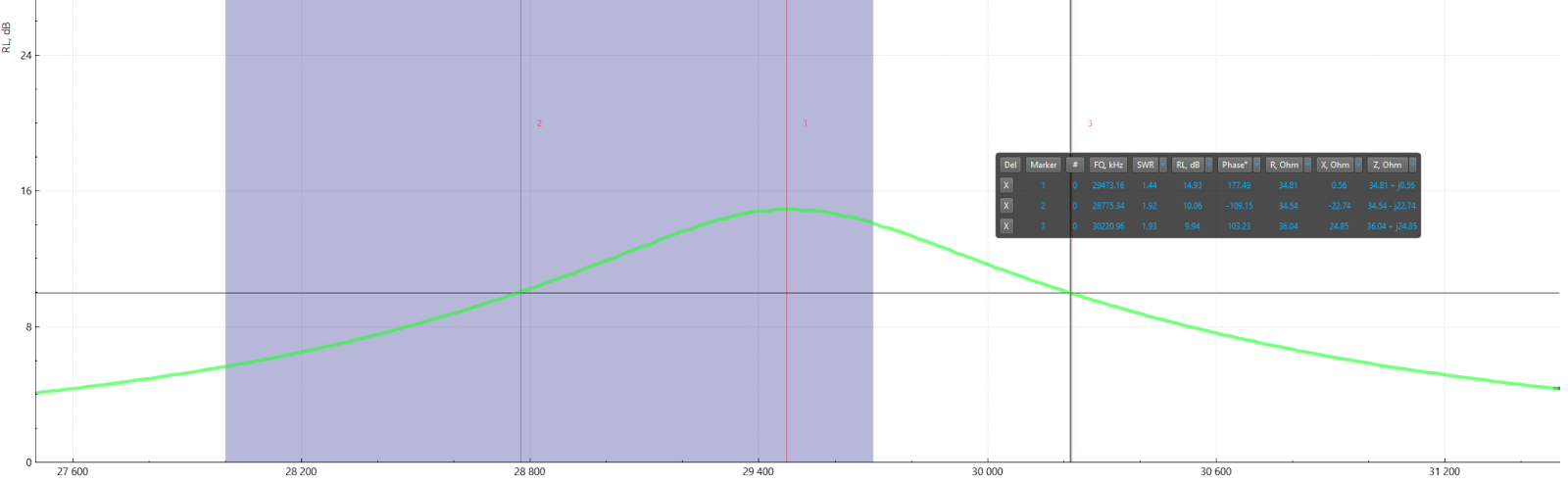
The results, after some manual adjustment of the base loading inductor values, and the length of the whip, are promising: a 10 dB return loss bandwidth of 1.5 MHz was observed, from 28.7 MHz to 30.2 MHz, in addition to a desired reduction of length to 186 cm from 269 cm. This is illustrated below, and it well matches the 100 kHz channel which needs to be served by it, centered at 29.410 MHz.
During review of the results, it was suggested that the addition of the measurement instrumentation package at the top of the structure has substantial surface area and would have an effect on the result as placed at the "end" of the upper antenna element (the CubeSat body, if the system is thought of an off centre fed dipole) at the high Z point. Therefore, further validation of these results, with the instrument package inside PCBSat will be required, either in this same rooftop test setup, or as part of an airborne campaign utilizing a large multirotor craft in CfAR’s uncrewed air system fleet. Stay tuned for updates!