External Antenna Testing
October 27, 2025
Author: Levente Buzas VA7QF
The MARMOTSat team has completed an external verification campaign for the VHF and UHF antennas of the spacecraft. The objectives of the test campaign were to tune the VHF and UHF antennas to the IARU frequencies assigned to the mission, pattern the UHF antenna used to support the command and control link, and evaluate the impact of the deployables on the 3D pattern and input characteristics of the same UHF antenna.
The reason for focusing on the UHF antenna was two-fold. This antenna supports the command and control link to MARMOTSat, which makes it the most important antenna featured on the spacecraft. In addition, low frequency anechoic chambers able to support HF and UHF antennas are very difficult to come by. The chamber, and the external test facility, Antenna Test Lab of Raleigh, North Carolina was selected because of a history of measurements for CfAR’s ORCASat missions, as well as the convenience and professionalism offered by them. Unlike other facilities, they offer an easy, quote-free website, rapid turnarounds, and easy to disseminate results, which make them ideally suited to serve academic CubeSat developers.
The test was conducted using a mock-up dubbed “PCBSat”, shown below. This article is an accurate representation of MARMOTSat in terms of what the antennas see, allowing the investigation of in-situ antenna performance. It consists of a 3D printed chassis, covered by FR4 PCBs, with copies of the flight VHF and UHF antenna subsystems mounted within, as well as a non-flight stub representing the HF antenna. Two configurations were tested, deployables open (left) and deployables closed <right>.


The first test consisted of tuning the VHF and UHF antennas, with the deployables open, to the frequencies assigned by the IARU to the mission. This was completed in the anechoic chamber, using a VNA, by physically trimming the antenna tape until minimum return loss was obtained at the frequency of interest. This resulted in the figures below.
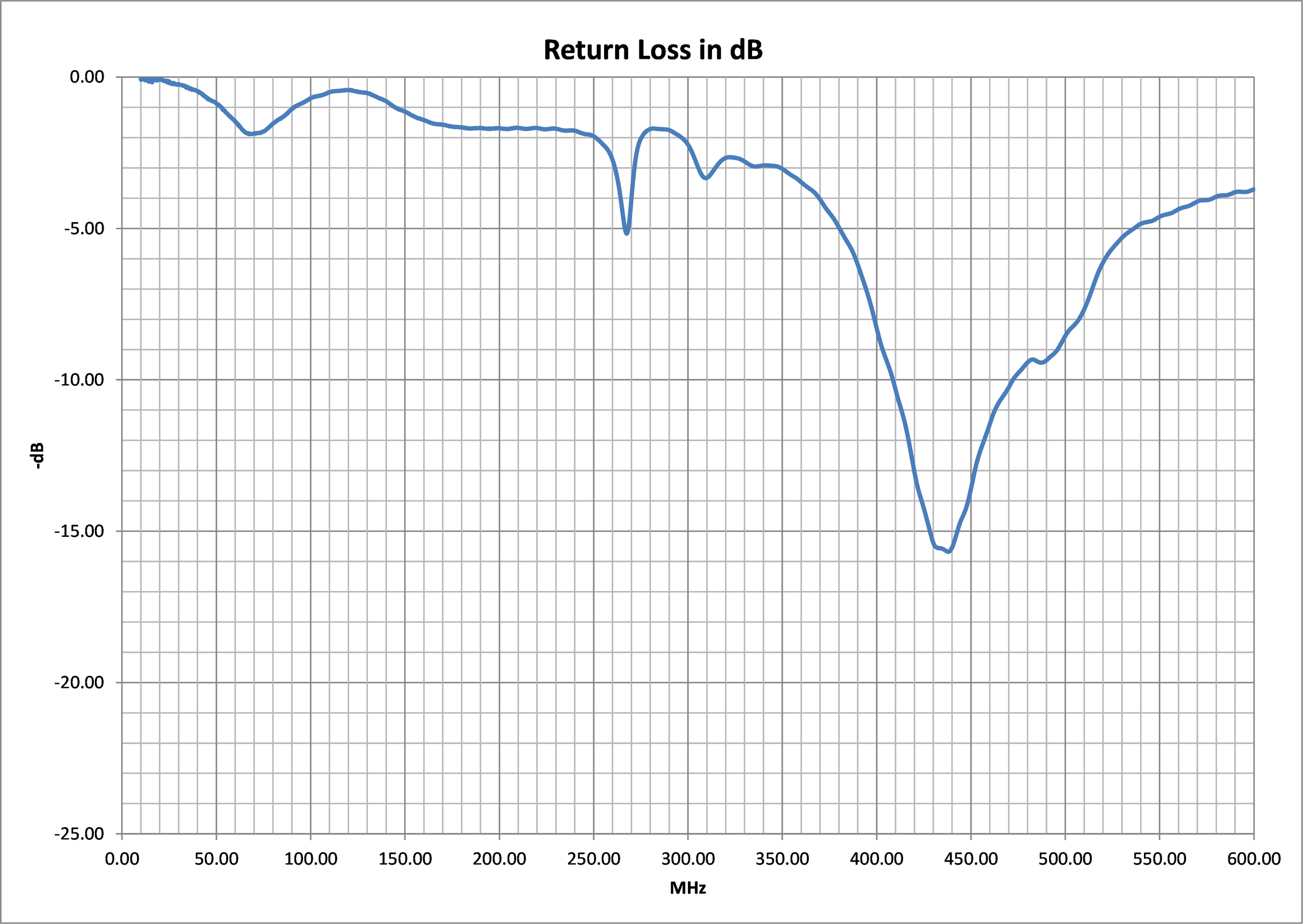
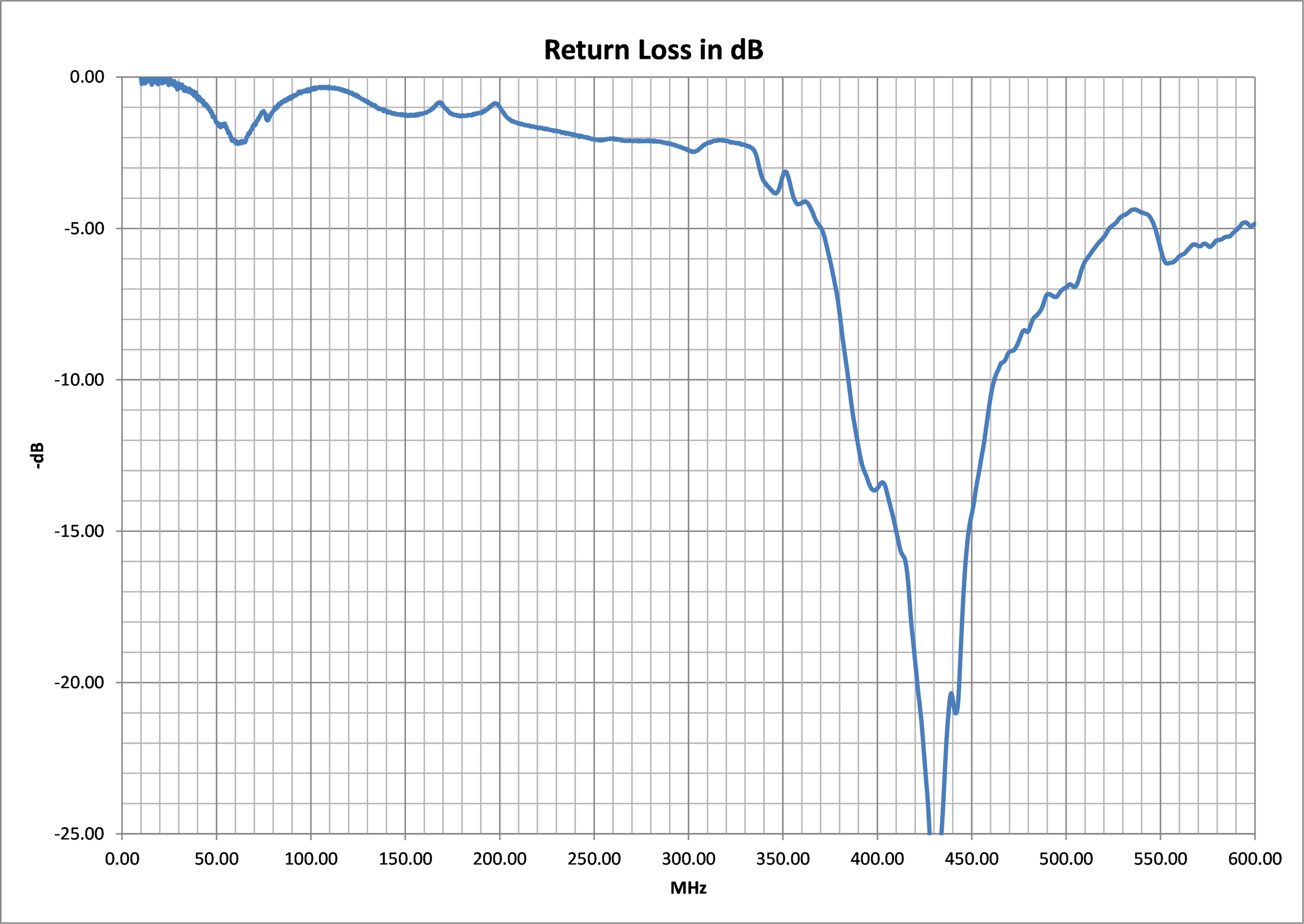
Open UHF Deployables Return Loss
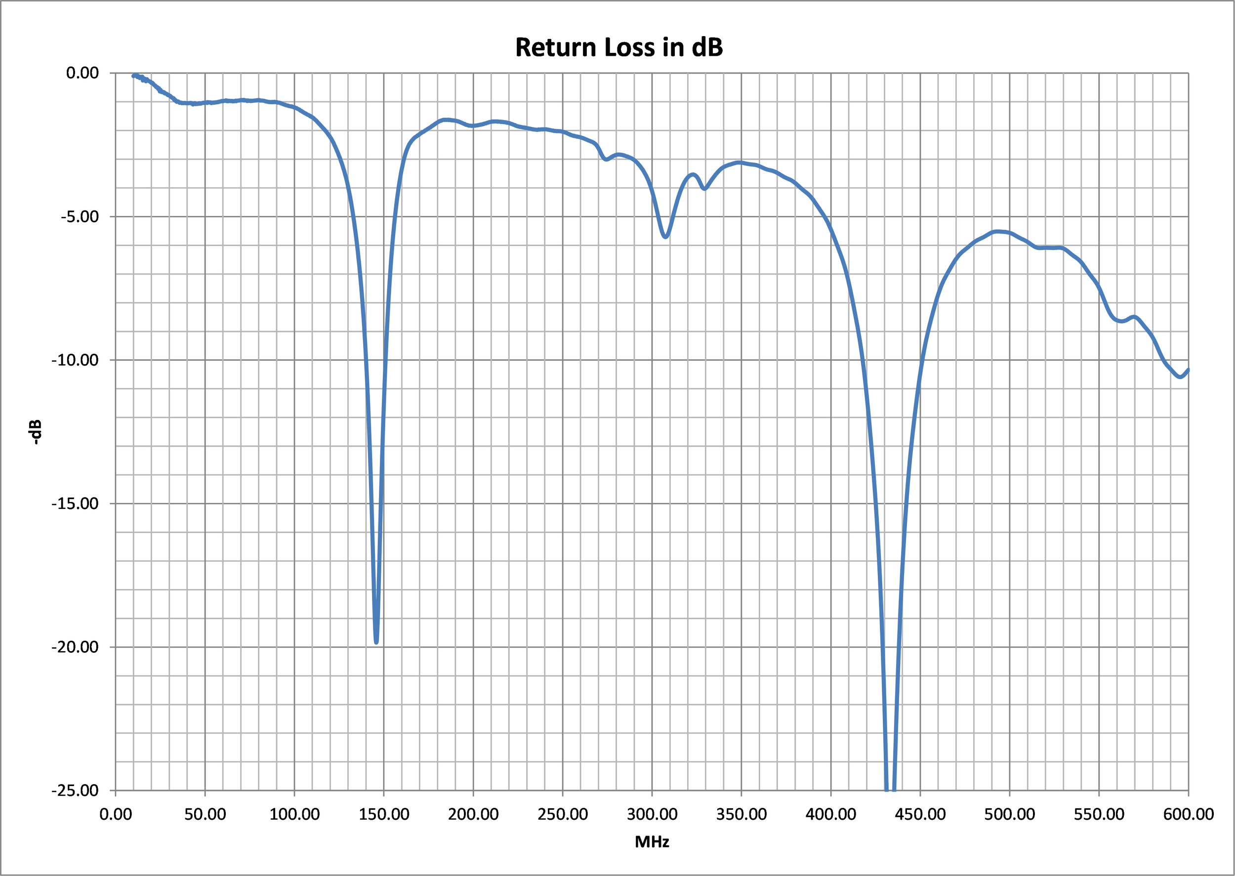
Open VHF Deployables Return Loss
These results indicate that the antennas have sufficient return loss to serve the power amplifier of interest, which can drive a -6 dB return loss load over all load angles. In addition, this return loss is also maintained over a wide frequency range (>10 MHz) for both antennas, which should guarantee adequate performance, even if additional detuning is experienced from the differences between PCBSat and MARMOTSat’s flight model.
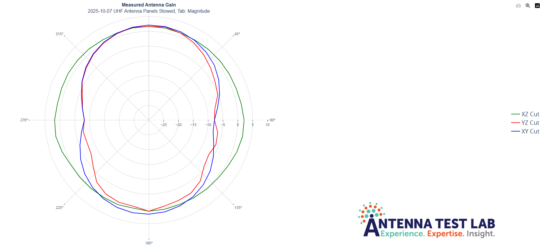
After tuning was completed the UHF antenna was patterned in an anechoic chamber, initially with deployables open. This was to validate the HFSS simulations of the directional characteristics of the UHF dipole given the distortion of the satellite body, and to make sure that the link budget assumption of minimum 0dBi gain in the direction of nadir is verified. In addition, from the pattern measurements, the efficiency of the antenna could be determined, and was of interest as well. The results of this are shown below.
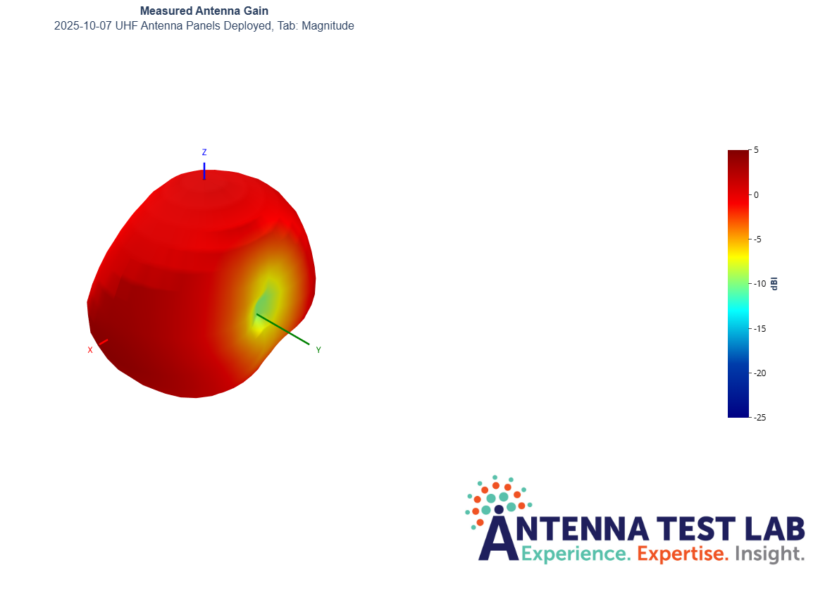
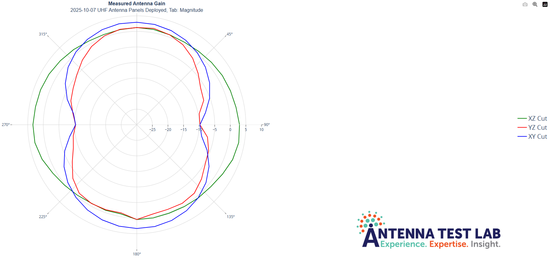
These results indicate that the desired performance is achieved, and from further mathematical analysis not shown here, it can also be ascertained that the antenna efficiency exceeds 95% at the frequency of interest, providing important real-life validation and confidence with regards to the correct operation of the MARMOTSat UHF command and control link.
Next, additional tests were conducted to evaluate the impact of the deployables on the input and 3D characteristics of the UHF antenna. According to the MARMOTSat CONOPS, initially, only the UHF antenna is deployed - followed by the rest of the deployables after first contact is made and the bus is commissioned. This means that the UHF antenna needs to work well both with and without deployables. To investigate this, the previous measurements were repeated with only the tuned UHF antenna deployed. This resulted in the data below.
Closed UHF Deployables Return Loss

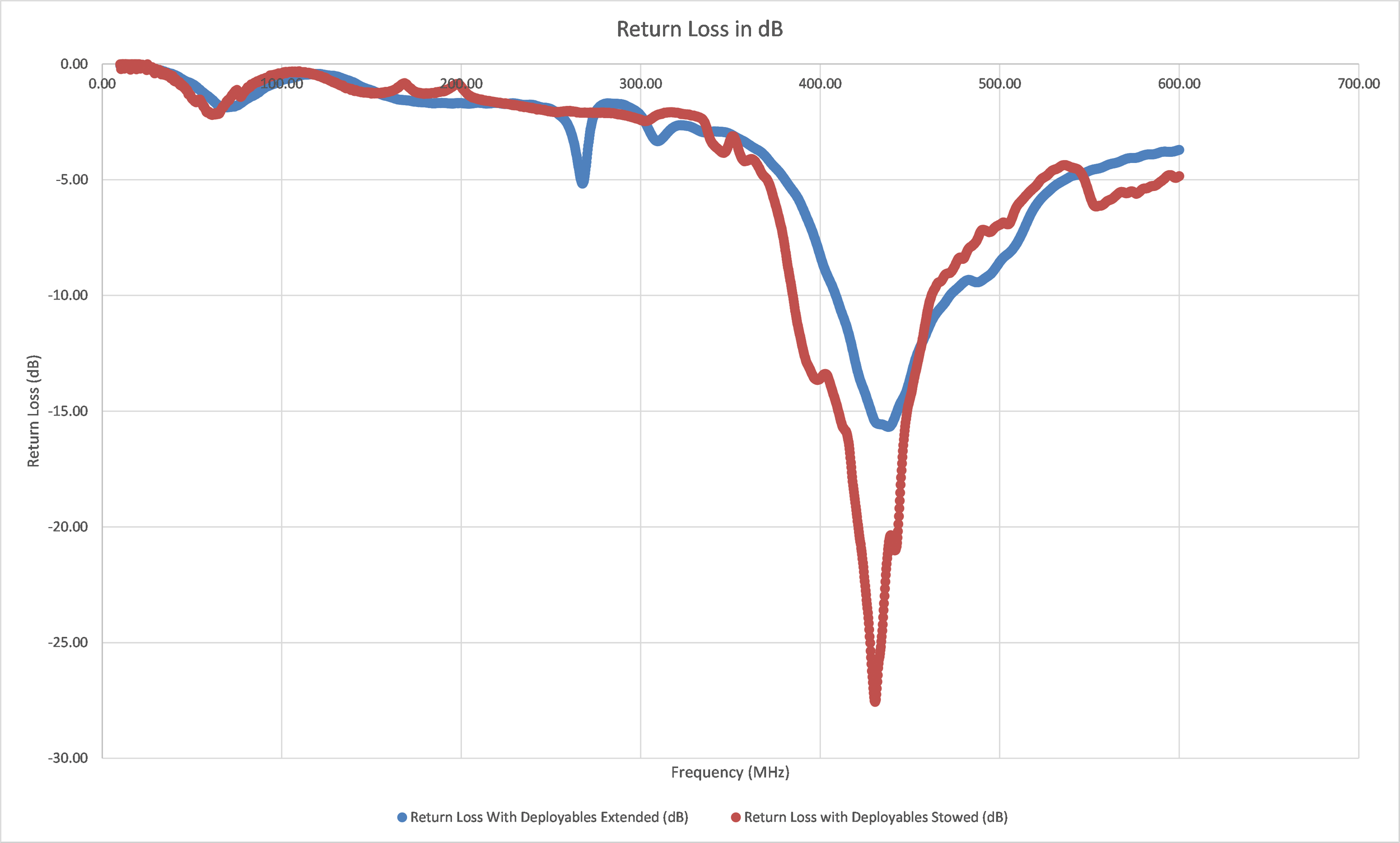
UHF Return Loss Comparison
As shown, while differences can be observed, these are not very significant, and will not adversely affect the link. Therefore, it can be concluded that the tested antenna configuration is ready for flight - stay tuned for additional updates, as we move ahead with the construction of the flight antenna batches.
UVic CfAR and the MARMOTSat team would hereby wishes to extend gratitude to Glenn KS4VA and Antenna Test Lab for their generous sponsorship of these measurements - we really appreciate your support!